Access Control System
An Access Control System (ACS) is a security solution designed to regulate who has access to certain areas or resources within a physical or digital environment. It encompasses a variety of technologies and methods to manage and restrict access to buildings, rooms, computer networks, data, and other sensitive assets.
In a physical sense, an Access Control System might involve traditional locks and keys, keycards, biometric scanners (like fingerprint or retina scanners), or electronic keypads. These systems can be integrated with alarms or surveillance systems for added security.
In a digital context, Access Control Systems manage user authentication and authorization for computer networks, databases, and software applications. This involves verifying the identity of users (authentication) and determining what resources or actions they are allowed to access (authorization). Digital access control often utilizes techniques such as passwords, cryptographic keys, multi-factor authentication, and role-based access control (RBAC).
INTRODUCTION
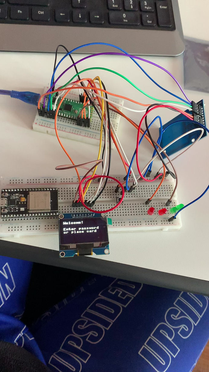
The access control system used in this case uses RFID and Pin identification in order to grant access. RFID, or Radio-Frequency Identification, operates through a system comprising RFID tags and reader devices. These tags, equipped with a microchip and antenna, come in various forms and hold unique identification data. When a reader device emits radio waves via its antenna, RFID tags within its range are powered up, activating and transmitting their stored information back to the reader. This communication allows for data retrieval and processing, enabling tasks such as verifying identity or triggering actions based on the received data. This project makes use of different modules at the same time in order to work
All the components and the program used are listed below:
Rasberry Pi pico
The Raspberry Pi pico is a microcontroller board with an RP2040 microcontroller chip. The Pico is notable for its low cost, small form factor, and versatility, making it suitable for a wide range of embedded projects and applications. It features a dual-core ARM Cortex-M0+ processor, ample memory, GPIO pins for interfacing with sensors and peripherals, and support for various programming languages, including MicroPython and C/C++.
The Raspberry was used in this project to process and store the information provided by the RFID tags as well as the Pin.

OLED DISPLAY
OLED, or Organic Light-Emitting Diode, displays are a type of screen technology that uses organic compounds to emit light when an electric current is applied. An OLED display module encompasses a compact electronic component that integrates an OLED display panel along with the necessary control circuitry and connectors into a single package. These modules provide an easy way to incorporate OLED technology into electronic projects without needing to deal with the complexities of designing and driving the display from scratch.
The OLED is used to monitor the processes in this project and also acts as an interface where the user can interact with the machine. It displays instructions such as "place the card" or "wrong pin try again"

RC522 RFID READER MODULE
The RC522 RFID module is a compact electronic component commonly used for RFID (Radio-Frequency Identification) applications. It is based on the MFRC522 integrated circuit and is capable of reading and writing RFID tags operating at 13.56 MHz frequency. The module typically consists of an antenna, control circuitry, and interface pins for communication with external microcontrollers or systems. It communicates with the host controller, in this case Raspberry Pi pico, via SPI (Serial Peripheral Interface) protocol.
When a user places their card on the reader, the module reads their ID and sends to the Rasberry Pi pico which compares it with the saved IDs and either sends an "Access Granted" or "Access Denied" message to the OLED

KEYPAD MODULE
A keypad is a user interface device commonly used for inputting numerical or alphanumeric data into electronic systems. It typically consists of a grid of buttons, each representing a specific character, digit, or function. Keypads may vary in size and layout, ranging from simple numeric keypads with 10 buttons (0-9) to more complex alphanumeric keypads with additional symbols and special function keys.
Keypads are often interfaced with microcontrollers or electronic devices using digital input/output pins or communication protocols such as I2C or SPI. When a button is pressed, it generates an electrical signal that can be detected by the connected system. The system can then interpret the signal to determine which button was pressed and take appropriate action based on the input.
In this project, the keypad was used to input the pin of the user if they opt to use their pin instead of the Card

SERVO MOTOR
A servo motor is a type of rotary actuator that is used to precisely control the angular position of its output shaft. It consists of a motor coupled with a sensor for feedback and a control system. The control system interprets the feedback from the sensor and adjusts the motor's position accordingly, allowing for accurate and controlled movement.
Servo motors are commonly used in various applications where precise positioning or continuous rotation is required, such as robotics, automation, remote control systems, and industrial machinery.
In this project, the servo motor is used to close and open the door lock. When it recieves an "Access Granted" signal from the Raspberry Pi pico, it turns and opens the door lock while it stays locked when it receives an "Access Denied" signal.

PROGRAM CODE
from machine import Pin, SPI
from ssd1306 import SSD1306_SPI
from mfrc522 import MFRC522
import framebuf
import utime
b1 = Pin(14, Pin.IN, Pin.PULL_DOWN)
b2 = Pin(15, Pin.IN, Pin.PULL_DOWN)
spi = SPI(0, 100000, mosi=Pin(19), sck=Pin(18))
oled = SSD1306_SPI(128, 64, spi, Pin(17),Pin(20), Pin(16))
#oled = SSD1306_SPI(WIDTH, HEIGHT, spi, dc,rst, cs) use GPIO PIN NUMBERS
reader = MFRC522(spi_id=0,sck=2,miso=4,mosi=3,cs=1,rst=0)
red = Pin(13, Pin.OUT)
green = Pin(12, Pin.OUT)
oled.text("Initialising...", 0,0)
oled.show()
utime.sleep(2)
oled.fill(0)
oled.show()
oled.text("Designed by Aura",0,0)
oled.show()
utime.sleep(1)
oled.fill(0)
oled.show()
utime.sleep(1)
oled.text("Welcome!",0,0)
oled.text("Enter pin or", 0, 20)
oled.text("place card", 0,30)
oled.show()
while True:
i = 0
j = 0
p = 0
reader.init()
(stat, tag_type) = reader.request(reader.REQIDL)
if stat == reader.OK:
(stat, uid) = reader.SelectTagSN()
if stat == reader.OK:
card = int.from_bytes(bytes(uid),"little",False)
#print("CARD ID: "+str(card))
if card == 494770414:
print("Access Granted. Welcome Home!")
oled.fill(0)
oled.show()
green.value(1)
oled.text("Access Granted!", 0,0)
oled.show()
utime.sleep(1)
green.value(0)
else:
print("Access Denied. Get out of here!")
oled.fill(0)
oled.show()
red.value(1)
oled.text("Access Denied!", 0,0)
oled.show()
utime.sleep(0.1)
red.value(0)
utime.sleep(0.1)
red.value(1)
utime.sleep(0.1)
red.value(0)
utime.sleep(0.1)
red.value(1)
utime.sleep(0.1)
red.value(0)
utime.sleep(0.1)
red.value(1)
utime.sleep(0.1)
red.value(0)
elif b1.value():
while b1.value():
i=i+1
oled.fill(0)
oled.show()
oled.text(str(i), 0,0)
oled.show()
utime.sleep(0.5)
if i == 5:
oled.fill(0)
oled.show()
oled.text("Access Granted!", 0,0)
green.value(1)
oled.show()
utime.sleep(1)
green.value(0)
elif i ==0 :
oled.fill(0)
oled.show()
oled.text("Welcome!",0,0)
oled.text("Enter pin:", 0, 20)
oled.show()
utime.sleep(1)
else:
oled.fill(0)
oled.show()
oled.text("Incorrect", 0,0)
red.value(1)
oled.show()
utime.sleep(0.1)
red.value(0)
utime.sleep(0.1)
red.value(1)
utime.sleep(0.1)
red.value(0)
utime.sleep(0.1)
red.value(1)
utime.sleep(0.1)
red.value(0)
utime.sleep(0.6)
oled.fill(0)
oled.show()
oled.text("Try Again", 0,0)
oled.show()
utime.sleep(0.5)
else:
oled.fill(0)
oled.show()
oled.text("Welcome!",0,0)
oled.text("Enter pin or", 0, 20)
oled.text("place card", 0,30)
oled.show()
utime.sleep(0.4)
This program code depends on two libraries which are needed to be stored in the pico before running the program. The two libraries are ssd1306 for the OLED display and mfrc522 for the RC522 RFID module